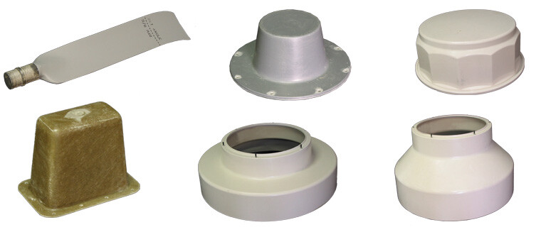
Hand Lay-Up (Open Molded)
The hand lay-up method is one of the oldest and most time-tested techniques in the fiberglass manufacturing process. Despite its simplicity, it remains highly relevant for certain applications where other molding methods are not cost-effective. Since 1972, Arrowhead has utilized hand lay-up to manufacture custom fiberglass-reinforced plastic (FRP) parts for industries including marine, transportation, and commercial equipment.
This process uses a single-sided mold where dry fiber reinforcement—typically fiberglass, carbon fiber, or Kevlar®—is manually placed. The fiber is then saturated with a thermoset resin, usually polyester, vinyl ester, or epoxy. Using specialized laminating tools, operators work the fiber and resin into the mold surface, ensuring full saturation, conformity to shape, and proper fiber-to-resin ratio.
The name “hand lay-up” comes from this manual placement technique. The resin may be applied manually or sprayed using a chopper gun. After application, the laminate is rolled out to remove trapped air and consolidate the layers. Once cured, the material forms a strong, rigid part.
When a finished cosmetic surface is required, the process begins by applying gel coat to the mold surface. The fiberglass laminate is then built up from the outside in—starting with the gel-coated layer and followed by reinforcing layers of resin-saturated fiber. Depending on structural needs, multiple layers may be applied to achieve the desired thickness and performance.
Though considered one of the more basic steps in the fiberglass manufacturing process, hand lay-up remains a flexible and cost-effective solution. It can accommodate complex shapes and varying material combinations and is well suited to lower-volume production where manual craftsmanship offers superior quality and control.
Resin Transfer Molding (RTM Closed Molding)
Resin Transfer Molding (RTM) is a versatile, closed mold technique in the fiberglass manufacturing process where liquid thermoset resin is injected under pressure into a sealed mold cavity containing dry fiber reinforcement. When a cosmetic finish is required, both mold halves can be pre-treated with gel coat; otherwise, the part can be molded without an in-mold coating. The two halves of the mold are clamped together—either by perimeter clamps or a press—and the resin is introduced, thoroughly saturating the fiber and filling the mold.
 RTM supports a wide variety of tooling. For low-volume production, room-temperature composite molds may be used, while high-volume runs often require temperature-controlled metal molds that enable faster cycle times. This flexibility makes RTM a go-to option for both prototyping and mass production.
As part size or complexity increases, so do the requirements for reinforcement loading and structural tooling strength. The RTM process is particularly beneficial for creating fiberglass parts with consistent wall thicknesses, high-quality surface finishes, and dimensional accuracy—ideal for performance-critical applications in transportation, agriculture, and more.
Spray-Up Process (Open Molding)
The spray-up process is a common open molding method in the fiberglass manufacturing process, ideal for creating large parts with complex shapes. It involves applying chopped fiberglass and resin simultaneously onto a single-sided mold using a specialized tool known as a chopper gun. The gun chops continuous fiberglass strands into short pieces and sprays them along with resin, producing a laminate with randomly oriented fibers.
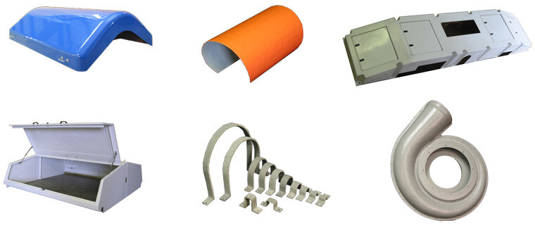 After the mixture is sprayed, laminators manually roll out the material to ensure it conforms to the mold’s contours. This helps compact the fibers, remove air pockets, and achieve the proper fiber-to-resin ratio. The result is a high-strength fiberglass reinforced plastic (FRP) part that can be adapted to many structural and cosmetic needs.
If a smooth, finished appearance is required, the process begins by applying a gel coat to the mold surface. The laminate is then built layer by layer from the outside in. Additional layers can be applied to meet structural requirements, and in some cases, the spray-up technique is combined with hand lay-up for added reinforcement.
While it’s one of the more basic methods within the fiberglass manufacturing process, spray-up is highly effective for low- to mid-volume production. It is widely used across the marine, transportation, and commercial sectors due to its versatility, low tooling cost, and adaptability to varied product shapes and sizes.
RTM Lite is a vacuum-assisted closed molding technique used in the fiberglass manufacturing process, offering a cost-effective way to produce strong, lightweight composite parts. This process uses a rigid mold on one side and either a lightweight rigid “B-side” mold or a vacuum bag on the other. Unlike traditional RTM, which relies on pressure to inject resin, RTM Lite uses vacuum to draw resin into the mold cavity.
The dry fiber reinforcement is first positioned in the mold. Once the mold is sealed—either with clamps or a vacuum bag—vacuum ports are opened, allowing resin to flow from its container into the mold. The vacuum ensures complete saturation of the fiber reinforcement and helps compress it before the resin arrives, resulting in a thin, high-fiber laminate.
One of the main advantages of RTM Lite in the fiberglass manufacturing process is its lower tooling cost. Because only one rigid mold half is required and the process uses vacuum instead of pressure, setup is simpler and less expensive. Gel coat surfaces can also be added for cosmetic finishes, making RTM Lite a great choice for efficient, high-quality production with minimal overhead.
Vacuum Infusion, also referred to as Closed Cavity Bag Molding (CCBM), is a specialized closed mold method in the fiberglass manufacturing process. This technique uses a rigid mold on one side and a flexible, reusable membrane on the other—often made from latex, silicone, or urethane. This membrane forms the vacuum-sealed cavity needed to infuse resin into the reinforcement layers.
During the process, dry fiber reinforcement is laid into the rigid mold. The flexible membrane is then placed over the mold, and vacuum is applied to fully seal the setup. Once sealed, vacuum ports are opened to draw resin into the mold cavity, ensuring the fibers are completely saturated. In some variations, low-pressure pumps assist the vacuum, increasing resin flow and reducing cycle time.
VIBM offers multiple benefits within the fiberglass manufacturing process. Because it only requires one rigid mold half and uses vacuum instead of pressure, tooling costs are relatively low. The reusable vacuum bag also reduces long-term operating costs compared to disposable bags. Additionally, this method captures fine details and complex geometries, delivering better back-side surface quality than traditional vacuum bagging.
The vacuum compression of fibers before resin infusion results in strong, lightweight laminates with excellent fiber-to-resin ratios. When combined with gel coats, this method is ideal for producing durable, cosmetically finished fiberglass components for applications requiring precision and repeatability.
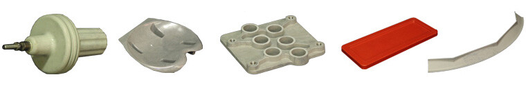
Compression Molding
Compression molding is a high-pressure, high-volume fiberglass manufacturing process ideal for producing complex parts with short cycle times. This method supports various material formats, including sheet molding compound (SMC), bulk molding compound (BMC), low-pressure molding compound (LPMC), and wet lay-up.
It delivers excellent part consistency, smooth surface finishes, and design flexibility—allowing for molded-in features like inserts, ribs, and bosses. The process can be automated, reducing labor costs and post-processing steps like trimming or machining.
Arrowhead specializes in short and small production runs using compression molding, offering a cost-effective, scalable solution for customers who need precision and repeatability at moderate to high volumes.

Compression Molding Tools
Compression molding tools include heated steel or aluminum molds mounted in high-pressure presses. These molds—single or multi-cavity—are typically heated to 250–350°F. In the fiberglass manufacturing process, matched metal molds enable high repeatability, support complex inserts, and deliver superior part quality, though they tend to cost more than traditional FRP open molds.
Let’s Talk About Whether SRTM is Right for Your Part
Silicone membrane resin transfer molding (SRTM) offers a clean, consistent way to produce fiberglass parts with less mess and more repeatability. At Arrowhead, we can help you determine whether SRTM or another fiberglass molding process is the best fit based on your part geometry, production volume, and finish requirements.
We also offer full trimming and finishing support with 5-axis CNC trimming to bring your part from mold to final spec.
Have a fiberglass part that might be a fit for SRTM?
Contact us today to get started.